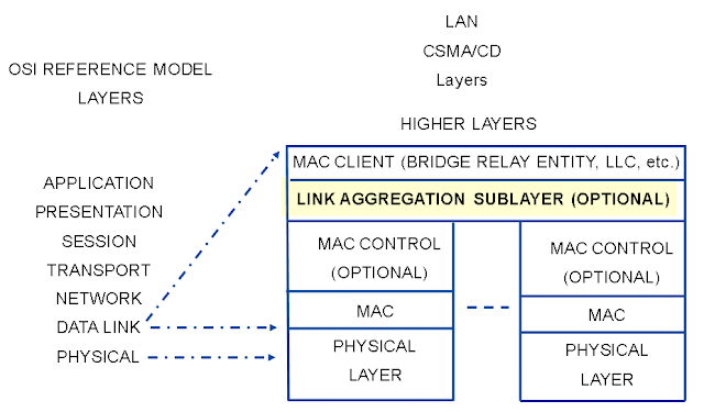
The 802.3ad standard supports aggregation on full duplex, point to point links, to form a Link Aggregation Group (LAG), so that a Media Access Control (MAC) Client can treat the LAG as if it was a single link.
The sublayer defines multiple functions like Link Aggregation Control (LAC), Link Aggregation Control Protocol (LACP).
LAC manages the Link Aggregation sub layer by static information local to the LAG groups, and dynamic information that is exchanged as part of the LACP. Each LAG group maintains config information to control and exchange the attributes of the bundle, maintains the ports connecting and disconnecting to the bundle and also controls the Aggregators collector, distributor functions.
In JUNOS, by default in a Link aggregation group (LAG), LACP is disabled. Following topics will look into LAG, its advantages and configuration . The following discussion will also cover the LACP function which can be enabled/disabled with LAG bundle.
The document will also cover the high availability feature that uses the LAG as redundant interfaces to provide LAG groups with failover properties.
IN 10.2 JUNOS version, LACP was introduced to use its benefits in a redundant interface setting and towards the end of the document it is discussed in detail. It is assumed that the reader of this document has basic understanding of SRX high end platform basic architecture. For details on certain topics and configurations, appropriate links are given in footnotes and endnotes.
WHY LINK AGGREGATION
Link Aggregation is a method which groups the multiple physical links to a single logical links for increased bandwidth.
This gives the advantage to increase the capacity and availability of communications between network devices using Ethernet technologies.
Higher link availability avoids the single point of failure of a physical link preventing from any traffic outage network scenario. If a member link goes down in a Link aggregation (LAG) group, it reduces the available capacity but traffic continues to flow through the other links without any interruption.
One of the other advantages with Link aggregation is use of load balancing where the forwarding and processing of traffic is distributed across member links of the LAG group. This avoids any one single physical link being overwhelmed with traffic.
JUNOS uses per packet load balancing algorithm for load balancing across LAG interfaces. The hash is based on SrcIP, DstIP, Protocol, SrcPort, DstPort, incoming interface index, and Type of service (ToS). The default option is to use Layer 3 header for load balancing hash. Layer 4 header can also be configured.
JunOS Configuration Walkthrough:
§ Chassis aggregated device counts specifies the number of LAG(AE/reth) groups defined. This config has to be deleted to take the interface out of the AE mode.
chassis {
aggregated-devices {
ethernet {
device-count 2;
}
}
}
§ Enable the aggregation on the ge-interfaces, All links are full duplex(1gbps in this eg.)
Map the physical member links to the Aggregated virtual links ae0 or ae1.
interfaces {
ge-0/0/0 {
gigether-options {
802.3ad ae0;
}
}
ge-0/0/1 {
gigether-options {
802.3ad ae0;
}
}
ge-0/0/4 {
gigether-options {
802.3ad ae1;
}
}
ge-0/0/5 {
gigether-options {
802.3ad ae1;
}
}
ge-0/0/6 {
gigether-options {
802.3ad ae1;
}
}
§ Ae0 and ae1 are lag groups 2 ge and 3ge member links resp. AE lags can have ports from only one node.
§ The minimum link is defined as 2 which implies that atleast 2 links must be up for bundle ae0 and ae1 to be up. The default is 1. The maximum is 16 which means all the member links should be up for AE bundle to be up.
§ Any physical property like link speed, vlan tagging, mtu, traceoptions will be defined within the two Aggregate interfaces, ae0 and ae1.
§ Aggregated-ether-options under AE interface hierarchy can be used to set some of the bundle properties.
§ AE interfaces can also carry untagged traffic. In the eg, ae0.0 is carrying traffic for vlan 201 and ae1.0 is carrying traffic for vlan 301.
ae0 {
aggregated-ether-options {
minimum-links 2;
}
vlan-tagging;
unit 0 {
vlan-id 201;
family inet {
address 10.10.10.1/27;
}
}
}
ae1 {
aggregated-ether-options {
minimum-links 2;
}
vlan-tagging;
unit 0 {
vlan-id 301;
family inet {
address 20.20.20.1/27;
}
}
}
§ The ae0 and ae1 have to be defined in security zones and permitted or denied by security policies.
zones {
security-zone trust {
host-inbound-traffic {
system-services {
ping;
}
}
interfaces {
ae0.0;
}
}
security-zone untrust {
address-book {
host-inbound-traffic {
system-services {
ping;
}
}
interfaces {
ae1.0;
}
}
}
Policies
{
default-policy {
permit-all;
}
Check the output of the interface with the following command:
root@ > show interfaces ae0 brief


No comments:
Post a Comment