This is a summary of the steps I took to create an Azure Palo Alto VM. It is basic for one instance scenario and not cover other complicated and advanced use cases.
In deploying the Virtual Palo Altos, the documentation recommends to create them via the Azure Marketplace (which can be found here: https://azuremarketplace.microsoft.com/en-us/marketplace/apps/paloaltonetworks.vmseries-ngfw?tab=Overview).Topology
Pre-requisites
1 Create Your Own Azure Account
2 Valid subscription, credits and deployment profile for authorization code
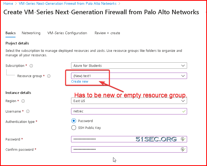
3 Create a Resource Group from Azure Portal (https://portal.azure.com)
Launch VM-Series Next Generation Firewall From Marketplace
1 Go to https://azuremarketplace.microsoft.com/ , click the button "Browse all Apps".
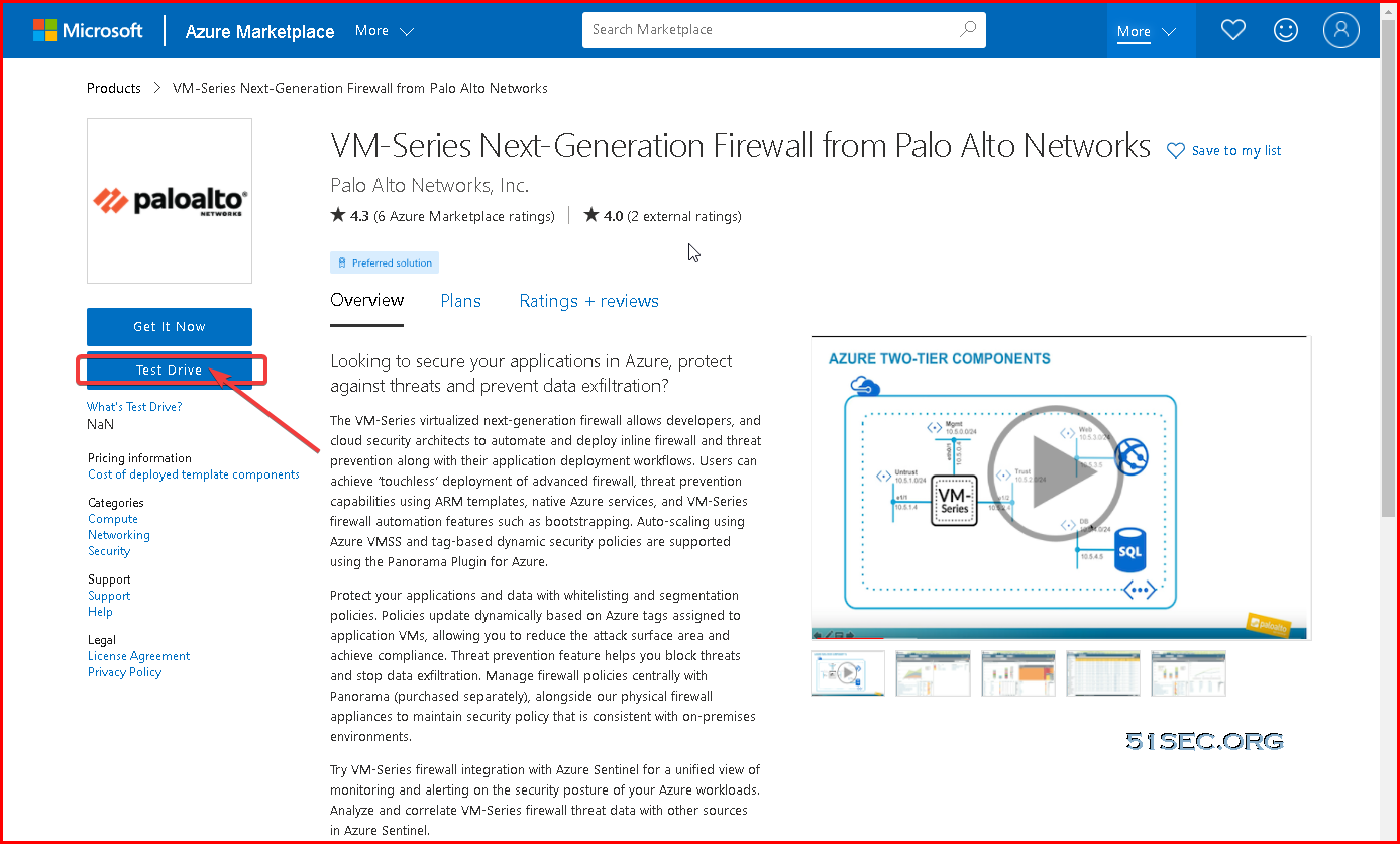
Or directly from this link: https://azuremarketplace.microsoft.com/en-us/marketplace/apps/paloaltonetworks.vmseries-ngfw?tab=Overview. There is a "Test Drive" option:
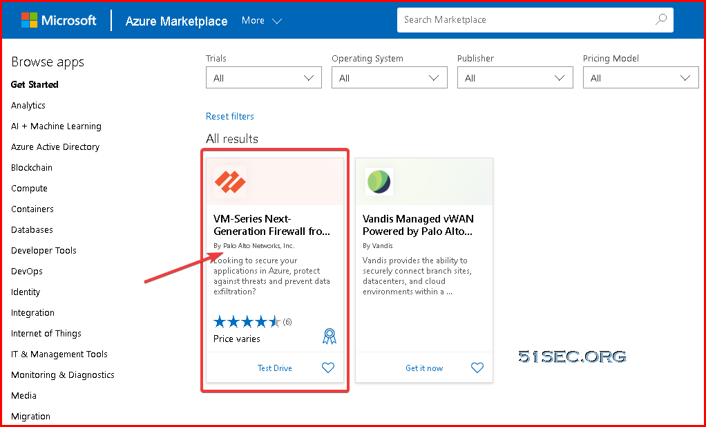
2 Search "Palo Alto VM" from top search textbox
By the way, from https://azuremarketplace.microsoft.com/en-us/marketplace/apps/paloaltonetworks.vmseries-ngfw?tab=Overview link, you also has an option to try it out.
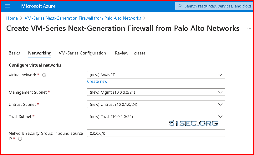
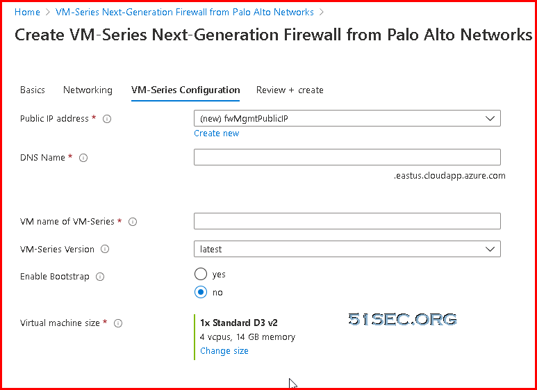
3 Follow screen option

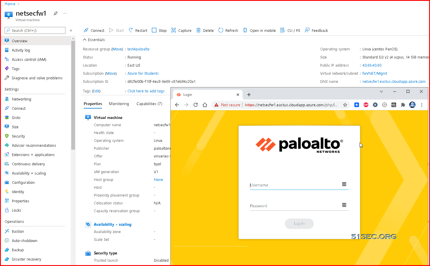
4 Wait until VM is fully up, then browse it using DNS name or IP address
Attach Public IP Address to Untrust Interface
- On the Azure portal, select the network interface for which you want to add a public IP address (such as theeth1interface).
- Select and, for Public IP address, selectEnabled. Create a new public IP address or select one that you have available.
Activate License
Follow these steps if using the BYOL version
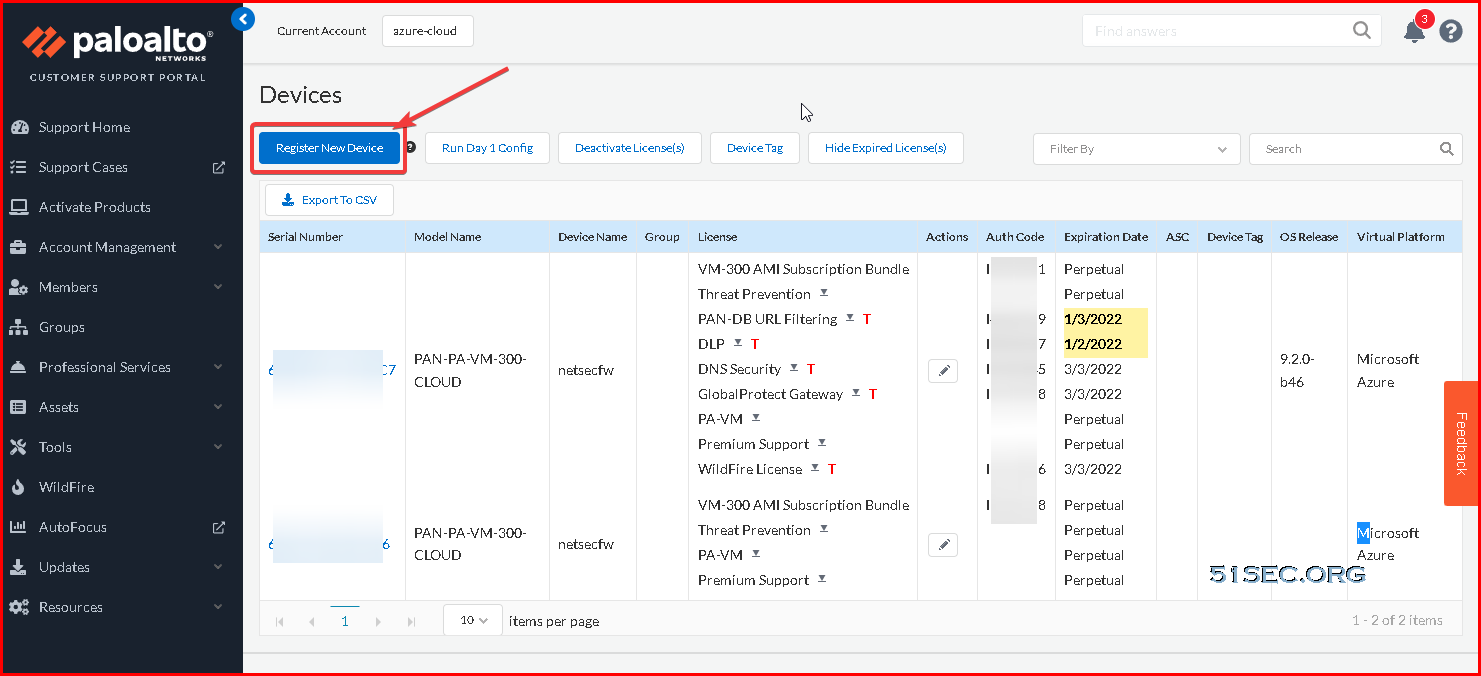
- Create a Support Account.
- Register the VM-Series Firewall
(with auth code). - On the firewall web interface, select Device tab -> Licenses
and select Activate feature using authentication code. - Enter the capacity auth-code that you registered on the support
portal. The firewall will connect to the update server (updates.paloaltonetworks.com), and download
the license and reboot automatically. If this doesn't work, please continue below to configuring the interfaces of the device. - Log back in to the web interface after reboot and confirm the following on the Dashboard:
- A valid serial number displays in Serial#.
If the term Unknown displays, it means the device is not licensed. To view
traffic logs on the firewall, you must install a valid capacity license. - The VM Mode displays as Microsoft Azure.
- A valid serial number displays in Serial#.

Follow these steps if using the PAYG (Pay as you go) version
- Create a Support Account.
- Register the Usage-Based Model of
the VM-Series Firewall in AWS and Azure (no auth code).
Configure Trust/Untrust Interfaces
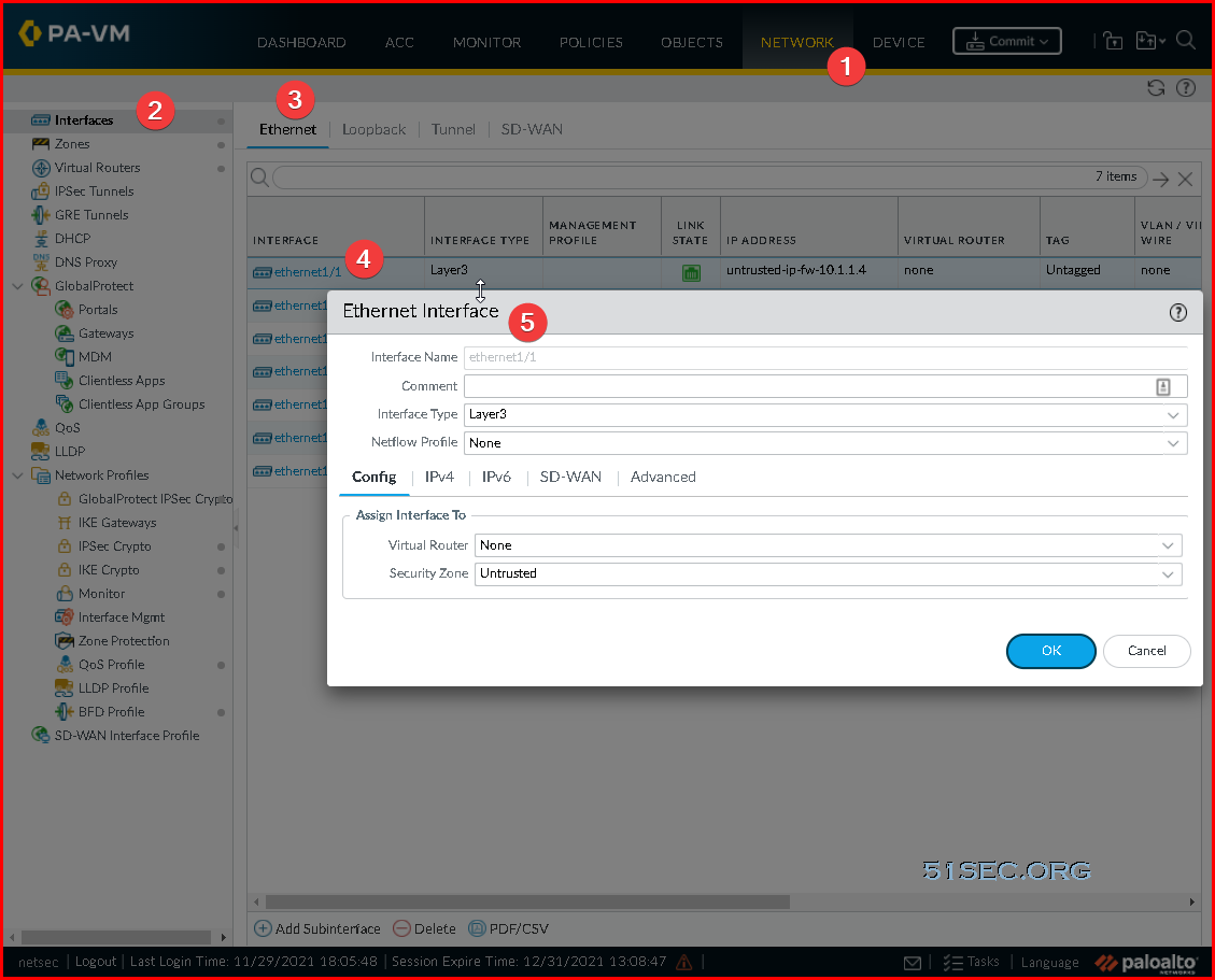
Configure the Untrust interface
- Select Network-> Interfaces ->Ethernet-> select the link for ethernet1/1 and configure as follows:
- Interface Type: Layer3 (default).
- On the Config tab, assign the interface to the Untrust-VR router. You might need to create a new Virtual Router here.
- On the Config tab, expand the Security Zone drop-down and select New Zone. Define a new zone called Untrust, and then click OK.
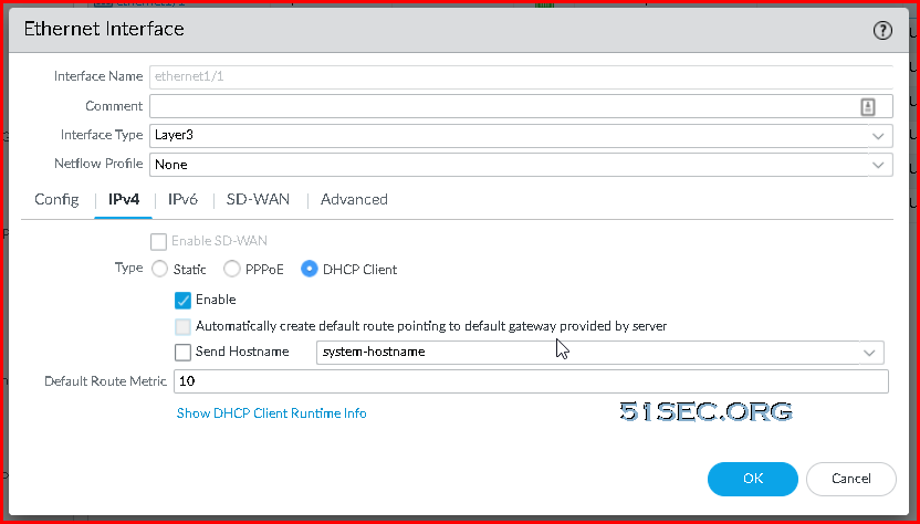
- On the IPv4 tab, select DHCP Client if you plan to assign only one IP address on the interface. If you plan to assign more than one IP address select Static and manually enter the primary and secondary IP addresses assigned to the interface on the Azure portal. The private IP address of the interface can be found by navigating to Virtual Machines -> YOURPALOMACHINE -> Networking and using the Private IP address specified on each tab.
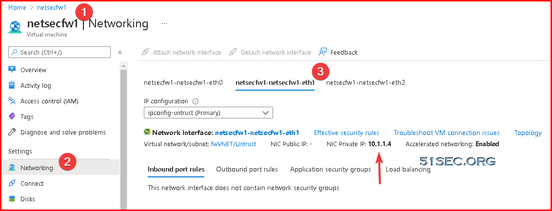
- Note: Do not use the Public IP address to the Virtual Machine. Azure automatically DNATs traffic to your private address so you will need to use the Private IP Address for your UnTrust interface.
- Clear the Automatically create default route to default gateway provided by server check box.
- Note: Disabling this option ensures that traffic handled by this interface does not flow directly to the default gateway in the VNet.
- Click OK
Note: For the untrust interface, within your Azure environment ensure you have a NSG associated to the untrust subnet or individual firewall interfaces as the template doesn't deploy this for yous per Azure Load Balancer's documentation, you will need an NSG associated to the NICs or subnet to allow traffic in from the internet.
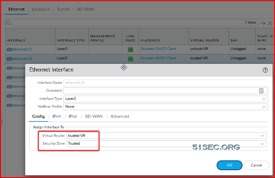
Configure the Trust Interface
- Select Network-> Interfaces ->Ethernet-> select the link for ethernet1/2 and configure as follows:
- Interface Type: Layer3 (default).
- On the Config tab, assign the interface to the Trust-VR router.
- On the Config tab, expand the Security Zone drop-down and select New Zone. Define a new zone called Trust, and then click OK.
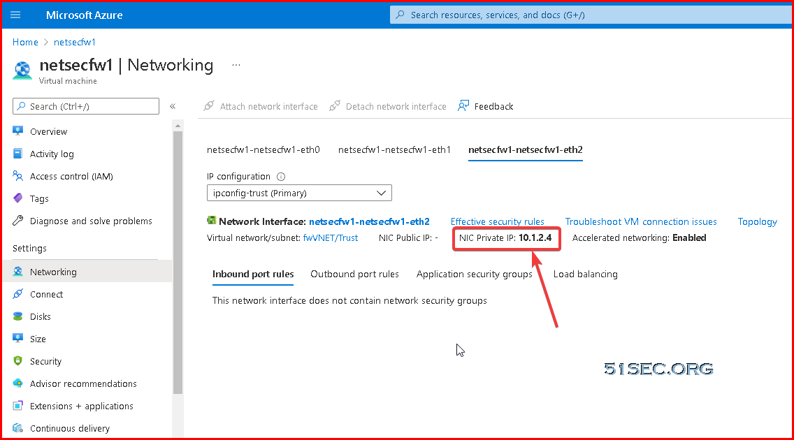
- On the IPv4 tab, select DHCP Client if you plan to assign only one IP address on the interface. If you plan to assign more than one IP address select Static and manually enter the primary and secondary IP addresses assigned to the interface on the Azure portal. The private IP address of the interface can be found by navigating to Virtual Machines -> YOURPALOMACHINE -> Networking and using the Private IP address specified on each tab.
- Clear the Automatically create default route to default gateway provided by server check box.
- Note: Disabling this option ensures that traffic handled by this interface does not flow directly to the default gateway in the VNet.
- Click OK
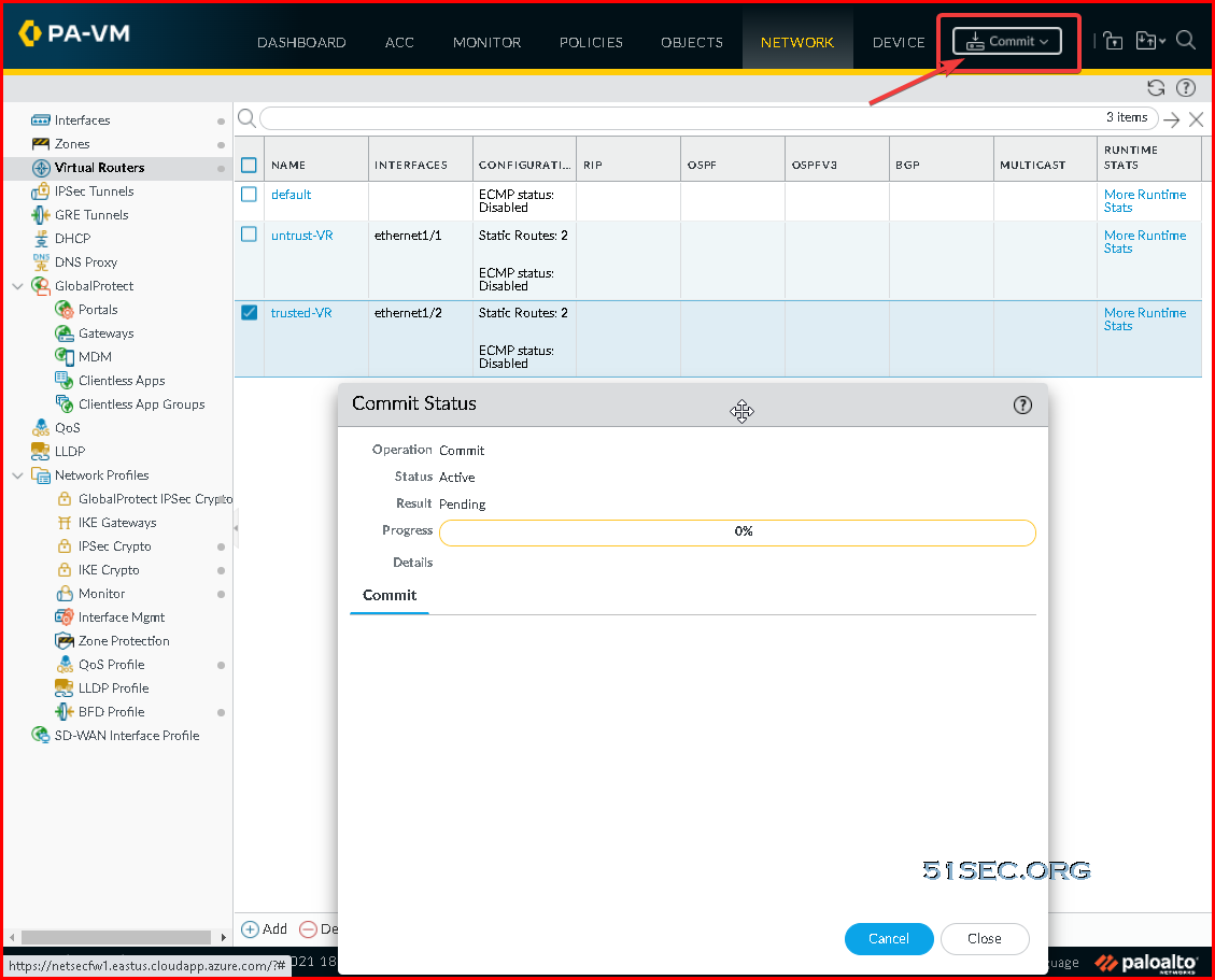
Click Commit in the top right. Verify that the link state for the interfaces is up (the interfaces should turn green in the Palo Alto user interface).
After Commit successful, your interfaces should get assigned IP addresses from Azure networking.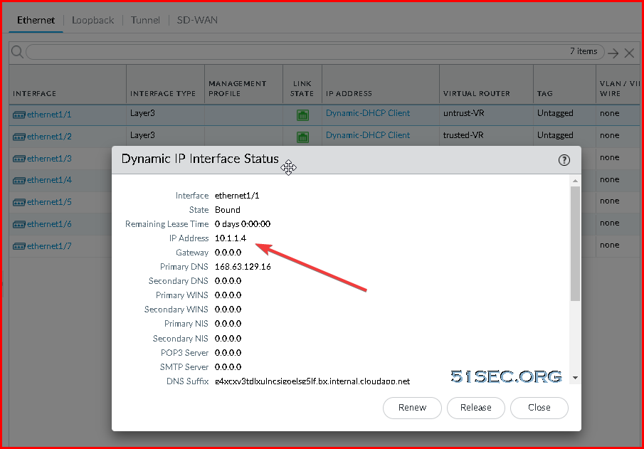
Define Virtual Routers and Static Routes
Untrust Virtual Router - Two static routes. (One for Internet, and another one for traffic going back to trust network.)
Trust Virtual Router - One static route. (All packets go to Untrust VR).
The Palo Alto will need to understand how to route traffic to the internet and how to route traffic to your subnets. As you will see in this section, we will need two separate virtual routers to help handle the processing of health probes submitted from each of the Azure Load Balancers.
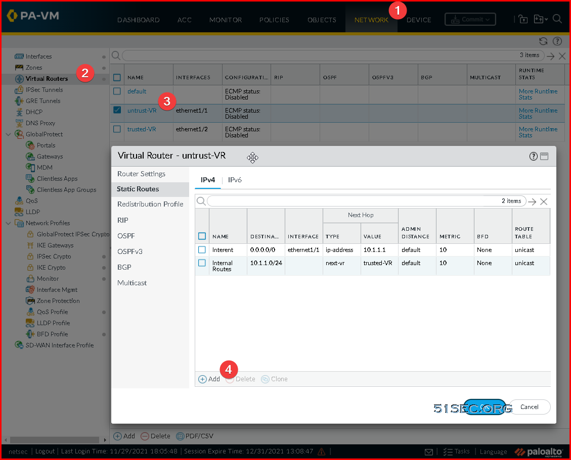
Create/modify a new Virtual Router and Static Route to the internet
- Select Network -> Virtual Router
- Click Add at the bottom
- Set the Name to Untrust-VR
- Select Static Routes -> IPv4 -> Add
- Create a Static Route to egress internet traffic
- Name: Internet
- Destination: 0.0.0.0/0
- Interface: ethernet 1/1
- Next Hop: IP Address
- IP Address: Use the IP address of the default gateway of your subnet the Untrust interface is deployed on, e.g. 10.1.1.1
- Note: To find this, navigate to the Azure Portal (portal.azure.com) and select All Services -> Virtual Networks -> Your Virtual Network -> Subnets and use the first IP address of your subnet the untrust interface is on. For example, is the address range of my subnet is 10.1.1.0/24, I would use 10.1.1.1 as my IP address. If my subnet was 10.1.1.128/25, I would use 129 10.1.1.129 as my IP address
- Create a Static Route to move traffic from the internet to your trusted VR
- Name: Internal Routes
- Destination: your vnet address space
- Interface: None
- Next Hop: Next VR
- Trust-VR
- Click OK
Create/modify a new Virtual Router and Static Route to your Azure Subnets
- Select Network -> Virtual Router
- Click Add at the bottom
- Set the Name to Trust-VR
- Select Static Routes -> IPv4 -> Add
- Create a Static Route to send traffic to Azure from your Trusted interface
- Name: AzureVNet
- Destination: your vnet address space
- Interface: ethernet 1/2
- Next Hop: IP Address
- IP Address: Use the IP address of the default gateway of your subnet the Trust interface is deployed on, e.g. 10.1.2.1
- Note: To find this, navigate to the Azure Portal (portal.azure.com) and select All Services -> Virtual Networks -> Your Virtual Network -> Subnets and use the first IP address of your subnet the trust interface is on. For example, if the address range of my subnet is 10.5.15.0/24, I would use 10.5.15.1 as my IP address. If my subnet was 10.5.15.128/25, I would use 129 10.5.15.129 as my IP address
- Create a Static Route to move internet traffic received on Trust to your Untrust Virtual Router
- Name: Internet
- Destination: 0.0.0.0/0
- Interface: None
- Next Hop: Next VR
- Untrust-VR
- Click OK
Click Commit in the top right.
NAT Rule for Internet Traffic
You will need to NAT all egress traffic destined to the internet via the address of the Untrust interface, so return traffic from the Internet comes back through the Untrust interface of the device.
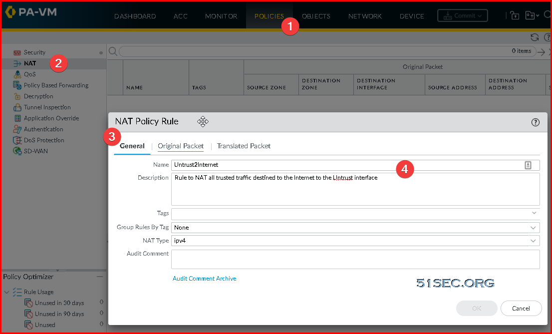
- Navigate to Policies -> NAT
- Click Add
- On the General tab use the following configuration
- Name: Untrust2Internet
- Description: Rule to NAT all trusted traffic destined to the Internet to the Untrust interface
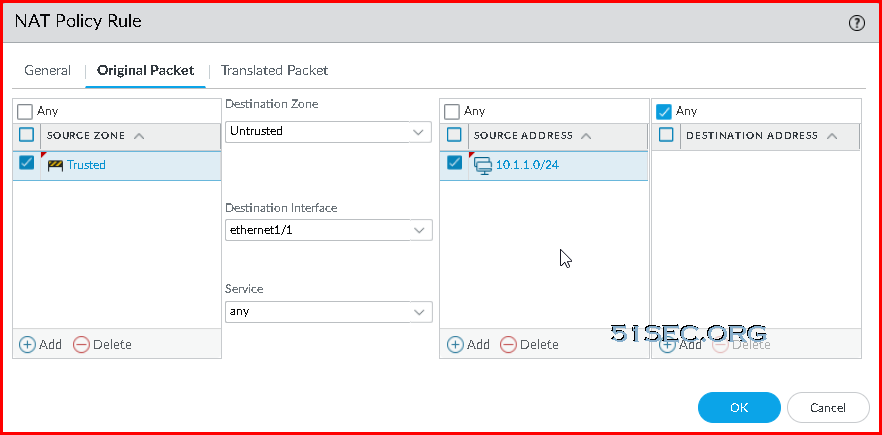
- On the Original Packet tab use the following configuration
- Source Zone: Click Add and select Trust
- Destination Zone: Untrust
- Destination Interface: ethernet 1/1
- Service: Check Any
- Source Address: Click Add, use the Internal Address space of your Trust zones, e.g. 10.1.2.0/24
- Destination address: Check Any
- The source address should be 10.1.2.0/24 (trusted network) , not 10.1.1.0/24 (untrusted)
- On the Translated Packet tab use the following configuration
- Translation Type: Dynamic IP and Port
- Address Type: Interface Address
- Interface: ethernet 1/1
- IP Address: None
- Destination Address Translation Translation Type: None
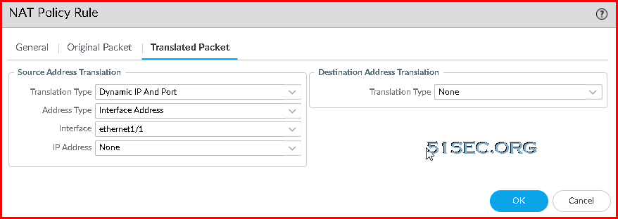
- Click OK
Click Commit in the top right.
Create Security Policy Rules for Your Traffic
Test
ping 8.8.8.8- Use the show session allcommand to view the session table, where you can verify the source IP address and port and the corresponding translated IP address and port.
- Use the show session id <id_number>to view more details about a session.
- If you configured Dynamic IP NAT, use the show counter global filter aspect session severity drop | match natcommand to see if any sessions failed due to NAT IP allocation. If all of the addresses in the Dynamic IP NAT pool are allocated when a new connection is supposed to be translated, the packet will be dropped.
Packets Capture
You might need to enable packet capture from Web GUI.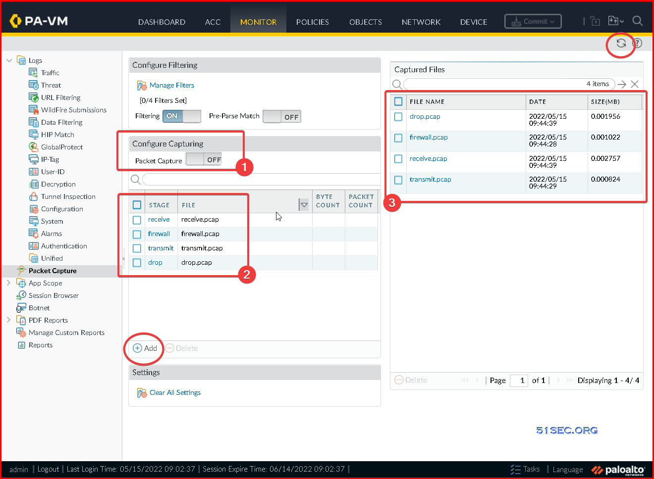


No comments:
Post a Comment