This post is to summarize the steps how to create VPN tunnels using Fortigate.
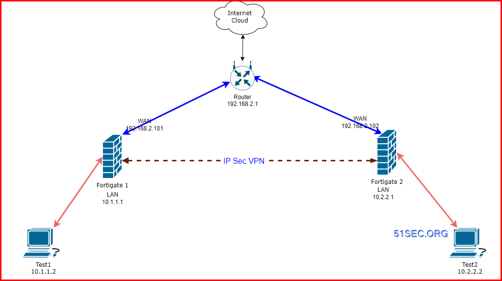
Diagram
- https://docs.fortinet.com/document/fortigate/7.4.0/best-practices/368512/ipsec-vpn
- https://docs.fortinet.com/document/fortigate/7.4.3/administration-guide/33578/configurable-ike-ports - if port 500 and 4500 blocked by ISP, you can enable NAT for other port, such as 5000.
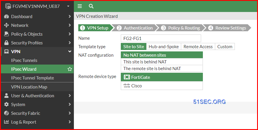
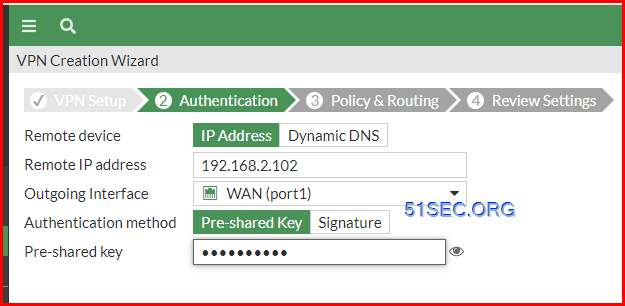
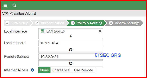
Create A Route Based VPN between FGs Using Wizard
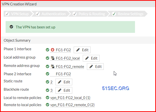
1. Create a basic FG vpn to FG vpn
All changes on the firewall:
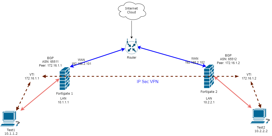
Manul Create A Route Based VPN with BGP
1 Create VPN using Custom Wizard
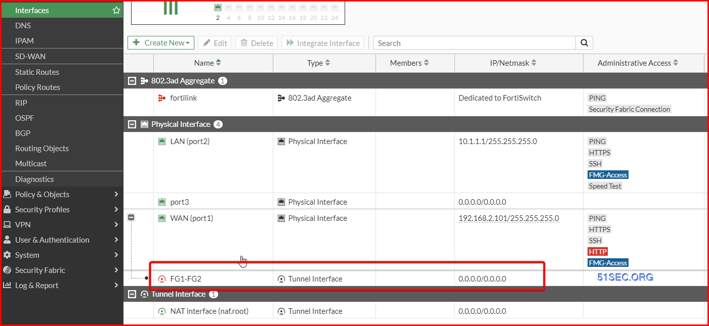
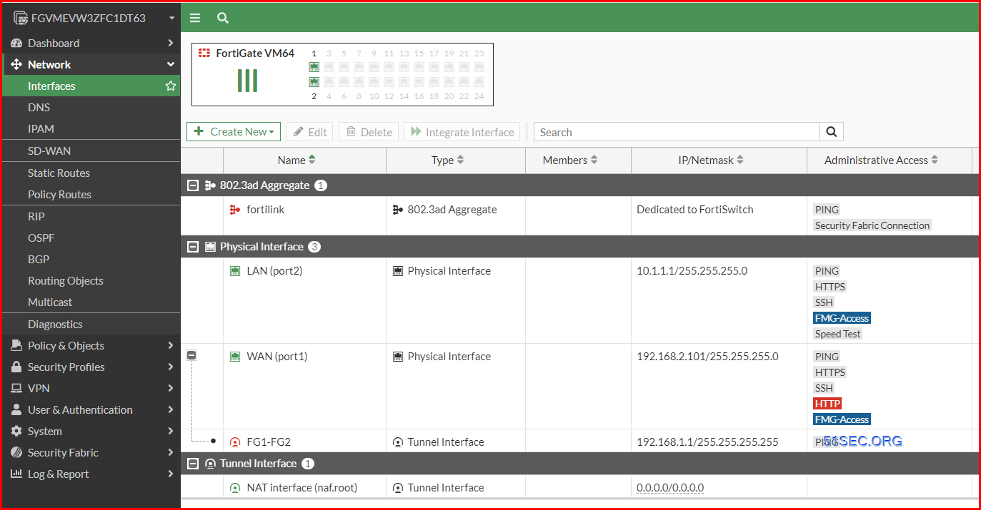
Assign IP Address to Your tunnel interface.
Please note if you are using a permanent evaluation license, your interface will be limited to only three, which also counts in your tunnel interface. If you exceeded the 3 limitation, the extra interface such as your tunnel interface, the configured ip address will be lost after a reboot.
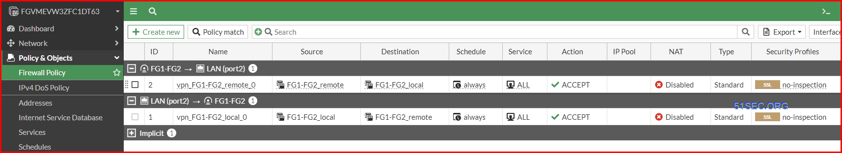
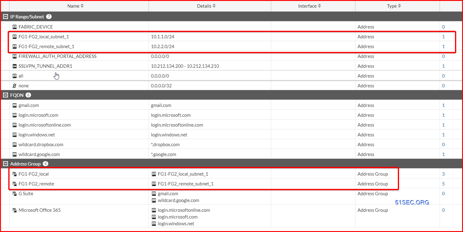
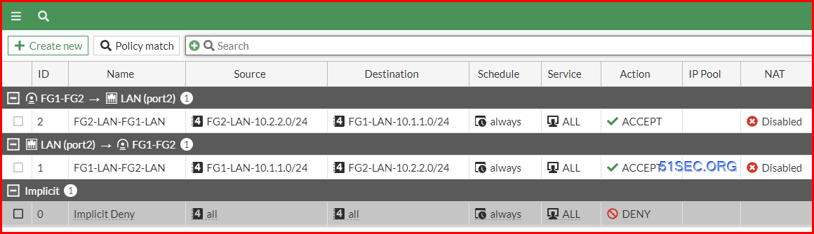
2 Create Security Policies Rules to allow VPN Traffic
Make sure the rules are coverning bidirection.
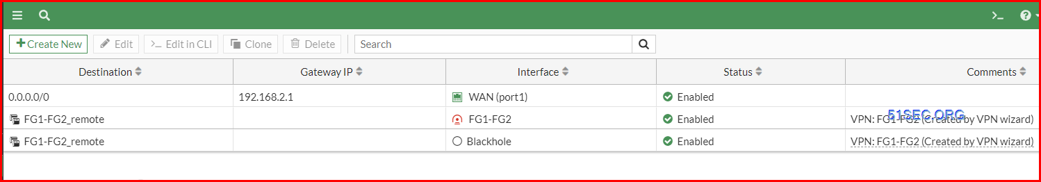
(Optional) Best Practice:
Create another route with the same Destination, but change the Administrative Distance to 200 and for Interface, select Blackhole. This is a best practice for route-based IPsec VPN tunnels because it ensures traffic for the remote FortiGate's subnet is not sent using the default route in the event that the IPsec tunnel goes down.

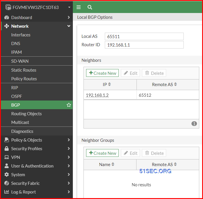
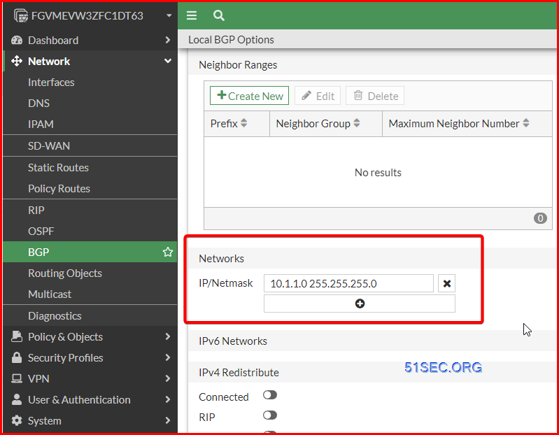
3 Enable BGP on Tunnel Interface
Local AS number: 65511
Router ID: (BGP ID) 192.168.1.1 (VTI IP)
Neighbor: Remote Peer BGP ID and Remote AS number: 192.168.1.2 65512
4 Test
BGP Related Commands
Configure BGP
- config router bgp
- get router info bgp summary
- get router info bgp neighbors
- get router info bgp network
- showing all networks with next hop, metric, locPrf, Weight, Path
- get router info routing-table bgp
- get router info bgp neighbors <neighbor IP> received-routes
- get router info bgp neighbors <neighbor IP> advertised-routes
- get router info bgp neighbors <neighbor IP> routes
- execute router clear bgp all soft in
- diagnose ip router bgp level info
- diag ip router bgp all enable
- diag ip router bgp show
- exec router clear bgp all
- diagnose ip router bgp all disable
- diagnose debug reset
Diag Commands
Diag BGP commands
- diagnose ip router bgp all enable
- diagnose ip router bgp level info
- diagnose debug enable
Diag VPN Tunnel commands
- diag debug enable
- diag packet sniffer
- diag debug app ike
- diag vpn tunnel list
- get vpn ike gateway <firewall name>
- get vpn ipsec tunnel name <tunnel name>
Diag BGP Traffic flow
# diagnose debug reset
# diagnose debug disable
# diagnose debug flow filter clear
# diagnose debug flow trace stop
# diagnose debug flow filter port 179
# diagnose debug flow show function-name enable
# diagnose debug flow trace start 454545
# diagnose debug flow show iprope enable
# diagnose debug console timestamp enable
# diagnose debug enable
To stop debugging.
# diagnose debug disable
# diagnose debug reset
# diagnose debug flow filter clear
# diagnose debug flow trace stop
Packets Capture Commands
- diag sniffer packet <interface> <'filter'> <verbose> <count> a
- <interface> can be an interface name or 'any' for all interfaces.
- <'filter'> is a very powerful filter functionality which will be described in more detail.
- <verbose> means the level of verbosity as described already.
- <count> the number of packets the sniffer reads before stopping. If there is no <count> value (or count=0), the Sniffer runs forever until stopped with <CTRL-C>.
- a – timestamps the packets with the absolute UTC time.
- l - (small letter L) timestamps the packets with LOCAL time on the unit.
- (blank/no letter) – relative to the beginning of the capture.
- diag sniffer packet port2 none 1 3
- diag sniffer packet any none 5 1
- diag sniffer packet wan1 'src 10.109.16.137 and net 172.26.48.0/20' 1 3
- diag sniffer packet wan1 'host 10.109.16.137 and host 172.26.48.0/20' 1 3
- diag sniffer packet wan1 'src 10.109.16.137 and tcp' 1 3
- diag sniffer packet wan1 'host 10.109.16.137 and host 172.26.48.21 and tcp port 80' 1 3
- diag sniffer packet any "host 10.10.10.10" 4 10
- 4 is verbose level 4
- 10 means 10 packets
Videos
Policy Based VPN vs Route Based VPN
General advice on VPNs: (from https://www.reddit.com/r/fortinet/comments/13i7jdm/eli5_routebased_vs_policybased/)
Use route based VPNs. they are the default in FortiGates.
Leave the proxy IDs as 0.0.0.0/0 (unless you want to be extra super secure), because the firewall policies should control which traffic is allowed to flow.
- A policy is created to define "interesting traffic". Interesting traffic will be routed across the IPSec tunnel.
- This policy should involve a Local Network (the source network) and a Remote Network (the destination network). It may also include source and destination TCP/IP ports, though this is less common.
- A pseudo-interface is created for the IPSec tunnel. This interface cannot be directly interacted with - i.e. the interface cannot be referenced in the zone firewall nor in route tables.
VTI (route-based) IPSec is supported by most security appliance providers and is the default option for some. VTI does not rely on a tunnel policy to define interesting traffic. Rather, a tunnel interface is created that behaves similarly to any other non-tunnel interface. Below is a fuller description of VTI's characteristics:
- IP Addressing - the tunnel interface will typically have an IP address. E.g. the tunnel interface may have an IP of 10.0.0.1/30. The peer's tunnel interface would then be 10.0.0.2/30. Users can test IP connectivity across the tunnel by pinging 10.0.0.2 from 10.0.0.1. To create an unnumbered interface, set the interface IP to 0.0.0.0.
- Security - tunnel can be referenced by the zone firewall. The tunnel interface can belong to a separate security zone and policies can be defined to control traffic flows across the tunnel interface
- Routing - static routes can be defined to use the tunnel interface. Dynamic routing protocols can use the tunnel interface. E.g. OSPF neighborships can be formed across the tunnel.
- Diagnostics - packet captures can be performed on the tunnel interface. This can be valuable when troubleshooting traffic flows across the tunnel.
For connecting multiple sites with unique subnets in a simple hub-and-spoke VPN topology, policy-based IPSec should be sufficient. Such a topology is illustrated below (note that there is no subnet overlap in the policy-based topology):
VTI is the recommended solution for creating a VPN mesh (partial or full) or when overlapping subnets are used. Such a topology is illustrated below:
VTI tunnel vs GRE tunnel
Step 1: Phase 1
show vpn ipsec phase1-interface
config vpn ipsec phase1-interface
    edit "PRI_REMOTESITE"
        set interface "port1"
        set peertype any
        set net-device disable
        set proposal aes256-sha256
        set dhgrp 2
        set remote-gw 66.16.164.26
        set psksecret ENC ROcEi7SM0.....Zg==
    next
Step 2: Phase 2
FGT # show vpn ipsec phase2-interface
config vpn ipsec phase2-interface
    edit "PRI_REMOTESITE"
        set phase1name "PRI_REMOTESITE"
        set proposal aes256-sha256
        set pfs disable
        set encapsulation transport-mode
    next
Step 3: GRE
NETSEC-FGT # show system gre-tunnel
config system gre-tunnel
    edit "PRI_GRE"
        set interface "PRI_REMOTESITE"
        set remote-gw 66.16.164.26
        set local-gw 10.254.3.5
    next
Step 4: Interfaces:
   edit "PRI_REMOTESITE"
        set vdom "root"
        set ip 10.254.3.5 255.255.255.255
        set type tunnel
        set remote-ip 66.16.164.26 255.255.255.255
        set snmp-index 7
        set interface "port1"

    edit "PRI_GRE"
        set vdom "root"
        set ip 172.31.255.254 255.255.255.255
        set type tunnel
        set remote-ip 172.31.255.253 255.255.255.255
        set snmp-index 9
        set interface "PRI_REMOTESITE"
Step 5: BGP
NETSEC-FGT # show router bgp
config router bgp
    set as 65515
    set holdtime-timer 30
    config neighbor
        edit "172.31.255.253"
            set capability-graceful-restart enable
            set ebgp-enforce-multihop enable
            set soft-reconfiguration enable
            set remote-as 22222
        next
        edit "172.31.255.249"
            set capability-graceful-restart enable
            set ebgp-enforce-multihop enable
            set soft-reconfiguration enable
            set remote-as 22222
            set route-map-out "OUT-TO-MPN"
        next
    end
    config network
        edit 1
            set prefix 10.254.0.0 255.255.0.0
        next
        edit 2
            set prefix 10.111.1.0 255.255.255.0
        next
    end
Step 6: BGP Related Configuration for Failover
Route-map and prefix-list
NETSEC-FGT # show router route-map
config router route-map
    edit "OUT-TO-MPN"
        config rule
            edit 1
                set match-ip-address "OUT-TO-MPN"
                set set-aspath "65515"
                unset set-ip-prefsrc
            next
        end
    next
end

NETSEC-FGT # show router prefix-list
config router prefix-list
    edit "OUT-TO-MPN"
        set comments "PRE-PEND"
        config rule
            edit 1
                set prefix 10.254.0.0 255.255.0.0
                unset ge
                unset le
            next
            edit 2
                set prefix 10.111.1.0 255.255.255.0
                unset ge
                unset le
            next
        end
    next
end
Step 7: Policy
References
- Check Point Route Based VPN
- https://yurisk.info/2010/03/26/fortigate-bgp-configure-and-debug/
- https://docs.fortinet.com/document/fortigate/6.2.16/cookbook/426761/site-to-site-vpn-with-overlapping-subnets


No comments:
Post a Comment